More Dynamometers Manufacturers
The term dynamometer can initially seem complex to those unfamiliar with industrial testing equipment. To simplify, a dynamometer derives from Latin roots: “dynamo” meaning “force, energy, or power,” and “meter” signifying “instrument for measurement.” In essence, a dynamometer is an instrument designed to measure force, torque, or power—making it indispensable in a wide array of engineering, automotive, aerospace, and industrial applications.
Applications of Dynamometers
Dynamometer systems are primarily used to test and measure the forces generated by engines and motors. Their core function—accurately capturing torque, rotational speed (RPM), and power output—makes them essential tools in research, development, quality assurance, and maintenance.
- Automotive Industry: Automakers rely on engine dynamometers and chassis dynamometers for performance tuning, emissions testing, and regulatory compliance. They are vital for simulating real-world driving conditions, measuring horsepower and torque curves, and ensuring vehicles meet Environmental Protection Agency (EPA) standards.
- Aerospace and Aviation: Aircraft engine manufacturers use advanced dynamometer systems to validate turbine, gearbox, and auxiliary power unit performance. Precision measurement ensures safety, reliability, and adherence to international aviation standards.
- Marine and Shipbuilding: Marine dynamometer systems test propulsion engines, thrusters, and gearboxes, verifying operational integrity under simulated sea conditions.
- Industrial Manufacturing: Dynamometers are essential for routine testing of electric motors, pumps, conveyors, and fluid power systems (hydraulic and pneumatic machinery). Accurate torque and power measurement optimize energy consumption, prevent equipment failure, and extend machine life.
- Research and Development: Engineering teams use dynamometers to prototype new products, analyze performance under various loads, validate computational models, and support innovative breakthroughs in motor and drivetrain technologies.
- Other Fields: Dynamometers play a crucial role in medical rehabilitation (hand-held dynamometers for muscle testing), material testing (tension and compression), and railways (testing locomotive engines and braking systems).
Are you searching for the right dynamometer for your application? What type of dynamometer is best for automotive testing, emissions measurement, or electric motor characterization? Explore our in-depth guides and manufacturer listings for tailored solutions.
History of Dynamometers
Dynamometers have a rich history dating back to the 18th century, when early scientists and engineers sought reliable methods for measuring mechanical power. The evolution of dynamometer technology reflects the growth of the industrial revolution, advances in material science, and the ever-increasing demand for precision in engineering.
One of the earliest examples, the Graham-Desaguliers Dynamometer, was developed by George Graham, a British clockmaker and geophysicist, and later improved by John Desaguliers, who documented it in 1719. In 1798, French engineer Edme Régnier introduced the Regnier dynamometer, paving the way for more accurate force measurement devices.
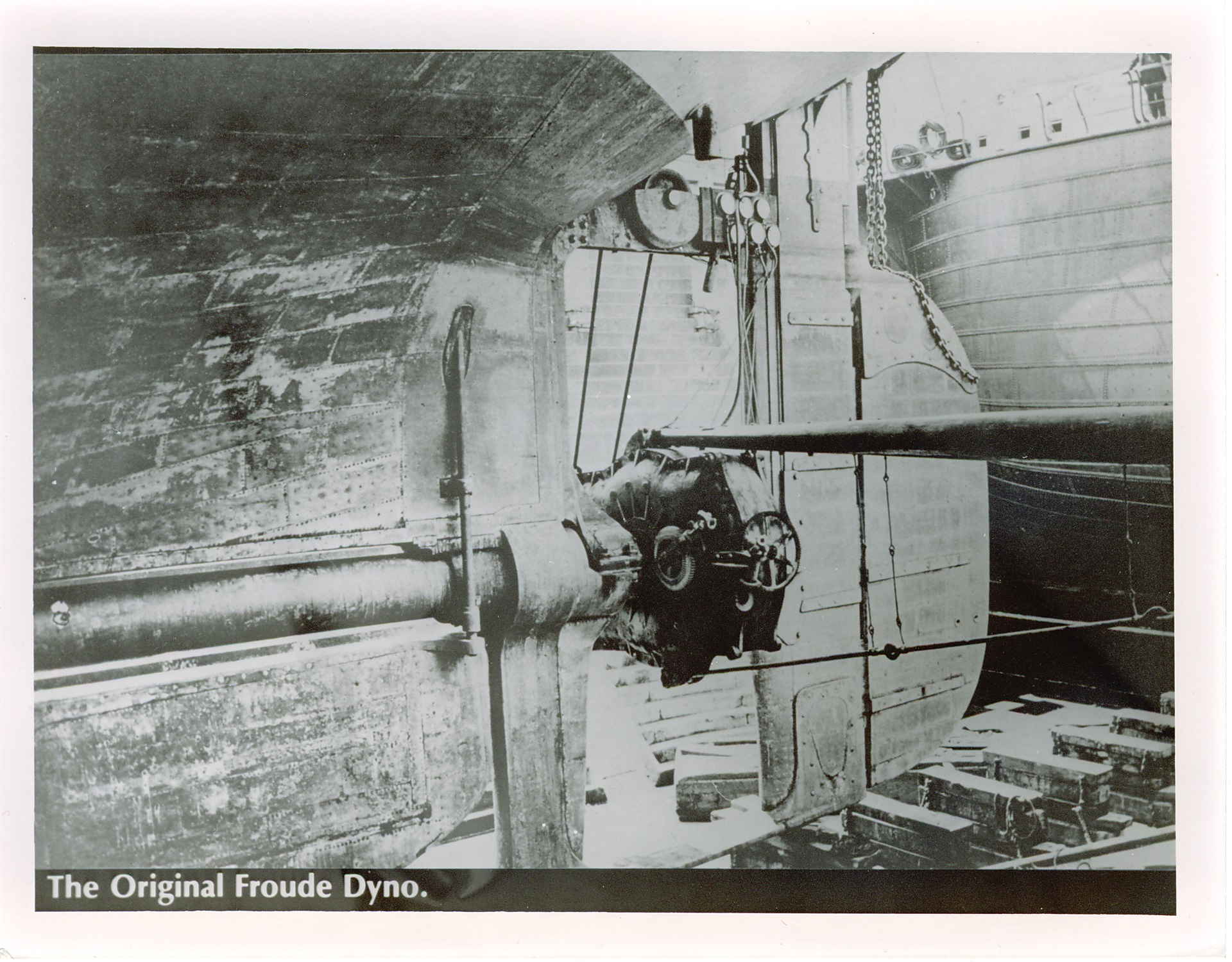
The 19th century saw the rise of notable inventions: the improved weight machine patented by Siebe and Marriot in 1817, the de Prony brake by Gaspard de Prony in 1821 (still foundational in brake dynamometer technology), Macneil’s road indicator by John Macneil in the late 1820s, and the hydraulic dynamometer by William Froude in 1877. The first commercial dynamometers emerged in 1881 by Heenan & Froude—today known as Froude, Inc. and Froude, Ltd.—which remain industry leaders in modern power measurement systems.
The early to mid-20th century marked a pivotal era for dynamometer innovation. Carl Schenck Eisengießerei & Waagenfabrik developed the first brake testing vehicle dynos in 1928, revolutionizing automotive testing. The introduction of DC motor dynos and the 1931 invention of the eddy current dynamometer by Martin and Anthony Winther for trains and railway brake systems reflected growing demand for dynamic load simulation.
Modern dynamometers now benefit from advanced machining, precision sensors, digital controls, and robust data acquisition systems. Today’s models are highly automated, compact, and customizable, able to meet unique specifications for automotive, industrial, research, and regulatory applications.
How Dynamometers Work
Dynamometers utilize a range of sophisticated technologies to provide highly accurate readings of force, torque, and rotational speed. The basic principle is to absorb or measure the power output of an engine or motor and convert that energy into a form that can be quantified and analyzed.
- Transducers and Strain Gauges: Many dynamometers incorporate transducers and strain gauges, which convert mechanical torque into electrical signals. These signals are then amplified, processed by digital controllers, and displayed on user interfaces for real-time analysis.
- Motor Testers: Motor testers use voltage and current probes connected to motor input wires. These connect to internal voltmeters, ammeters, and ohmmeters, allowing engineers to measure direction, torque, voltage, power, current, cut-out speed, and overall efficiency.
- Non-contact Speed Sensors: Optical or magnetic sensors measure motor drive shaft speed, capturing the number of rotations per minute (RPM) without physical contact, ensuring accuracy and minimizing wear.
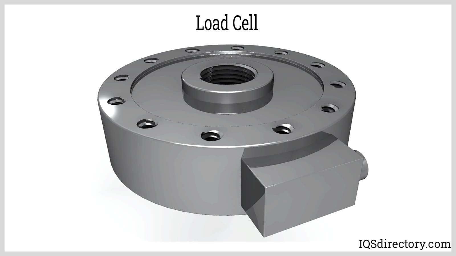
- Load Cells: These precision devices transform mechanical force into quantifiable electrical output, providing highly repeatable force and torque readings.
- Data Acquisition and Software: Modern dynamometers are integrated with advanced data acquisition systems and analysis software, enabling automated reporting, historical trend analysis, and remote diagnostics.
Curious about the differences between analog and digital dynamometer systems? How do advanced sensors improve measurement accuracy and reliability? Visit our detailed technical resources or contact a manufacturer for an expert consultation.
Types of Dynamometers
There are several main types of dynamometers, each designed for unique industrial, automotive, and research applications. Understanding the differences can help you choose the most suitable dynamometer for your requirements.
- Chassis Dynamometers: Chassis dynamometers measure vehicle wheel rotation, simulating real-world driving conditions to determine engine or motor torque, horsepower, and emissions. Vehicles are placed on stationary rollers, and computer software tracks performance across variable loads. Subtypes include:
- Inertia Dynamometers: Ideal for continuous, repeatable runs. Electric motors turn a flywheel mass (usually about a quarter of the test vehicle’s weight). When the flywheel reaches targeted RPM, braking forces are measured and analyzed to determine output.
- Hydraulic Dynamometers: Utilize a hydraulic fluid-filled casing to increase load, including a fluid reservoir, hydraulic pump, and adjustable valves. These provide the fastest load change capability, making them ideal for dynamic engine testing and research.
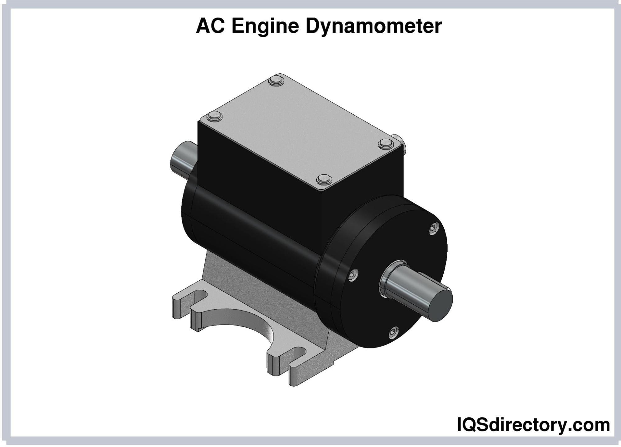
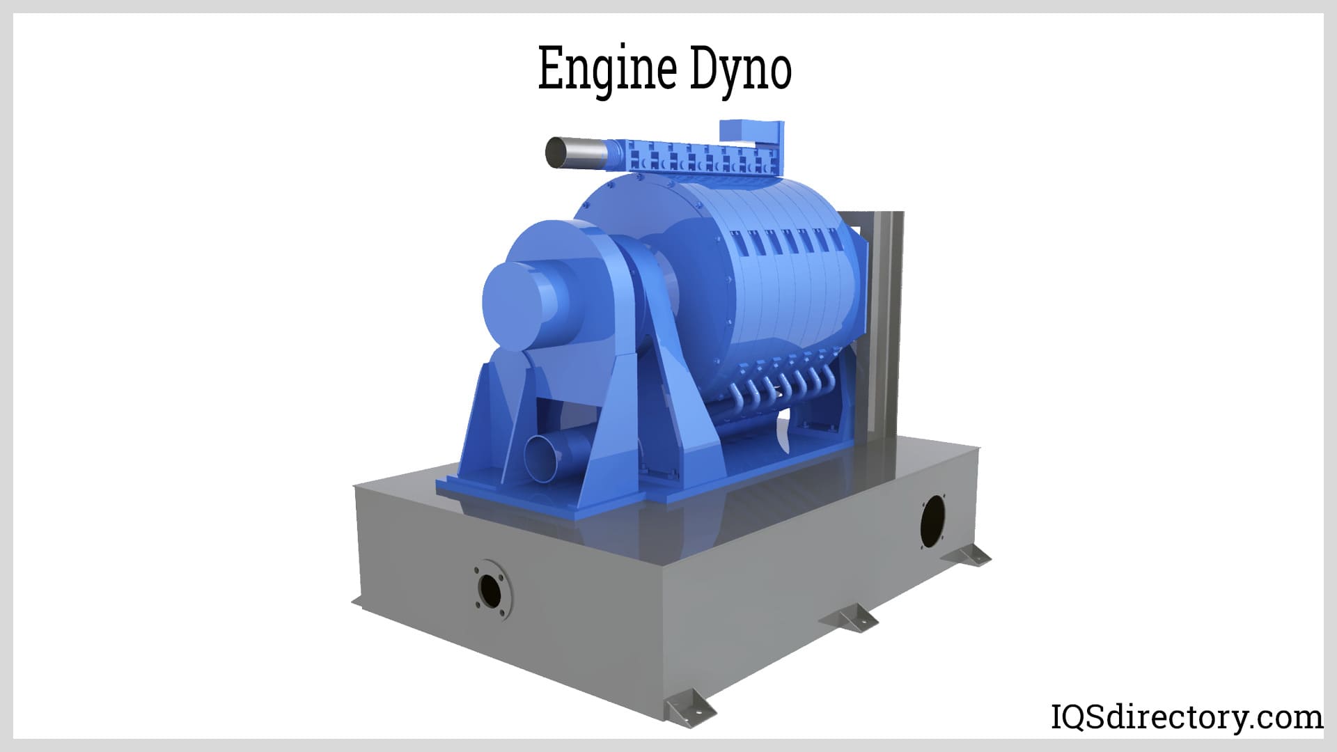
- Engine Dynamometers: Engine dynamometers measure power directly from the engine or electric motor. These units require engine removal from the vehicle and offer unmatched accuracy and repeatability. They are popular among engine rebuilders, automotive manufacturers, race car developers, and research labs. Subtypes include:
- Brake Dynamometers: Apply a controlled braking force to the engine output shaft, measuring torque response under varying load conditions. This provides detailed data on engine performance and durability.
- Eddy Current Dynamometers: A type of brake dynamometer, they use electromagnetic induction to generate a braking force. This enables precise, non-contact load control, making them ideal for high-performance and emissions testing. Learn more about eddy current dynamometers.
- PTO Dynamometers (Power Take-Off): Designed for agricultural and industrial vehicles, PTO dynamometers measure the power transferred from a tractor or truck’s PTO shaft to an attached implement, using eddy current technology for high accuracy.
- Spring Dynamometers: Simple yet effective, these devices use a calibrated metal spring to measure force through deformation. They are ideal for educational settings, small-scale testing, and force calibration applications.
- Absorption Dynamometers: Devices that absorb the entire power output of the engine or motor, dissipating energy as heat or through hydraulic resistance. These are often used in laboratory settings for precise analysis of engine behavior under load.
- Transmission Dynamometers: Measure the power transmitted through a drive system, such as a gearbox or shaft, often used in research and product development to optimize drivetrain efficiency.
Not sure which type of dynamometer fits your testing scenario? Compare chassis, engine, and absorption dynamometers in our comprehensive comparison guide, or contact our experts for personalized recommendations.
Components of Dynamometers
Despite the diversity in size, shape, and function, most dynamometers share several fundamental components:
- Absorption Unit or Driver: Typically a rotor or brake mechanism enclosed in a housing, this component absorbs or applies load to the engine/motor under test.
- Torque Production System: Generates and modulates torque, using friction, hydraulic fluid, or electromagnetic forces to create controlled resistance.
- Measurement Apparatus: Load cells, strain gauges, or force transducers convert mechanical force into electrical signals, enabling precise measurement of torque and rotational speed.
- Control System: Modern dynamometers feature programmable logic controllers (PLCs), data acquisition units, and digital displays for real-time monitoring and automated test sequencing.
- Safety and Cooling Mechanisms: Integrated fans, coolant systems, and thermal sensors ensure safe operation during high-power testing and prevent damage from overheating.
Want to know more about dynamometer components? How do load cells and strain gauges improve measurement accuracy in industrial dynamometers? Browse our technical articles or reach out for a detailed component breakdown.
How to Use Dynamometers
The procedure for using a test dynamometer varies by application, but generally follows a structured process:
- Setup and Configuration: Begin by securely mounting the engine, motor, or vehicle on the dynamometer test stand. Connect necessary sensors, cooling systems, and data acquisition devices.
- Control Panel Settings: Set the test mode—either Load Control (for steady-state power measurement) or Speed Control (for variable-speed testing). Modern systems allow for automated profile programming via software interfaces.
- Testing Sequence: With the throttle fully open and Speed Control engaged, start the engine at low speed and gradually increase RPM. Capture performance data at each interval, repeating as needed to determine optimal engine speed, torque, and efficiency.
- Monitoring and Safety Checks: Continuously monitor engine temperature, vibration, and exhaust emissions. Ensure all cooling mechanisms are operational to prevent overheating, which could skew results or damage equipment.
- Data Analysis and Reporting: Post-test, review collected data using integrated analysis software. Generate detailed reports for compliance, product development, or quality assurance.
Are you a first-time user? What are the best practices for safe and accurate dynamometer operation? Download our step-by-step usage guide or contact technical support for training options.
Benefits of Dynamometers
Dynamometers offer a range of advantages for manufacturers, engineers, and researchers:
- Performance Validation: Dynamometers enable precise measurement of engine and motor output before products reach the market. This ensures quality, reliability, and compliance with industry standards.
- Early Issue Detection: By identifying inefficiencies, performance anomalies, or mechanical faults (such as slow acceleration, excessive vibration, or faulty brakes), manufacturers can make adjustments before costly recalls or repairs arise.
- Enhanced Product Safety: Comprehensive testing with a dynamometer assures customers that products meet stringent safety and durability requirements, building brand reputation and reducing liability.
- Regulatory Compliance: Dynamometers are critical for emissions testing and EPA certification. They help manufacturers comply with environmental regulations by verifying that engines meet or exceed allowable emission limits.
- Environmental Sustainability: By optimizing engine efficiency, dynamometers contribute to lower fuel consumption and reduced emissions, supporting corporate sustainability goals and environmental stewardship.
- Automation and Productivity: Modern, automated dynamometer systems minimize human error, enable faster test cycles, and provide more accurate, repeatable results. This drives ongoing improvements in product development and operational efficiency.
- Cost Savings: Early detection of issues and optimization of system performance reduce long-term maintenance costs, warranty claims, and downtime.
Want to see real-world ROI? How have leading manufacturers leveraged dynamometers to improve product quality and reduce environmental impact? Check out our case studies and white papers for in-depth analysis.
Designing Dynamometers
Designing a dynamometer involves a careful balance of customer requirements, technical specifications, and industry standards. Leading manufacturers collaborate with clients to engineer solutions that fit precise testing needs, budget constraints, and spatial limitations.
- Customization: Manufacturers offer custom dynamometer designs, including tailored casings, mounting systems, sensor configurations, and software integrations. Whether you need a compact bench-top unit, a heavy-duty vehicle dyno, or a fully automated test cell, solutions are available to match any requirement.
- Compliance and Standards: Depending on your application, your dynamometer may need to comply with SAE International (Society of Automotive Engineers), ASTM International, or other industry-specific standards. SAE standards cover chassis, inertia, and brake dynamometers, while ASTM provides standardized testing methods for dynamic force and power measurement.
- Material Selection: The choice of durable, heat-resistant, and low-friction materials ensures long service life and consistent performance, even in harsh testing environments.
- Advanced Features: Modern dynamometers can include features such as remote monitoring, automated calibration, modular expansion, integrated emission analyzers, and real-time cloud data sharing.
Need help designing your custom test solution? What industry standards must your dynamometer meet for certification or regulatory approval? Consult with our engineering team or download our design checklist.
Choosing the Right Dynamometer Manufacturer
Acquiring a reliable, high-performance dynamometer system is a critical investment for any organization conducting engine, motor, or vehicle testing. The choice of manufacturer directly affects the accuracy, durability, and long-term value of your testing solution.
- Evaluate Experience: Choose a supplier with a proven track record in your industry—whether automotive, aerospace, marine, or industrial. Review case studies, certifications, and customer testimonials.
- Assess Customization Capabilities: Does the manufacturer offer custom solutions, rapid prototyping, or integration with your existing test infrastructure?
- Compare Technical Support: Reliable technical support, training, and after-sales service are essential for long-term success.
- Consider Budget and Lead Times: Request detailed quotes, compare pricing models, and clarify delivery timelines to ensure your project stays on track.
- Verify Compliance: Ensure all equipment meets relevant industry and government standards for accuracy, safety, and environmental impact.
We recommend exploring the dynamometer manufacturers listed on this page, each of whom has consistently demonstrated their reliability and technical expertise. Begin by comparing their services and products with your specific application requirements. Select three or four companies and reach out for a conversation or quote.
During these discussions, address key aspects such as budget, lead times, delivery preferences, custom options, and compliance with required standards. After evaluating their responses and customer service, choose the manufacturer that best aligns with your needs. Contact them to initiate the process and ensure your testing operations are equipped with the most advanced and reliable dynamometer technology.
Frequently Asked Questions About Dynamometers
- What is the difference between a chassis and engine dynamometer? A chassis dynamometer measures total vehicle output at the wheels, while an engine dynamometer measures power directly at the engine output shaft, providing unmatched accuracy for engine builders and researchers.
- How do dynamometers contribute to emissions testing and EPA compliance? By simulating real-world load conditions, dynamometers allow manufacturers to measure exhaust emissions, fuel consumption, and engine efficiency, ensuring compliance with environmental regulations.
- Can dynamometers be used for electric and hybrid vehicle testing? Yes. Modern dynamometers are equipped to test electric motors, hybrid drivetrains, and regenerative braking systems, capturing data crucial for the development of next-generation vehicles.
- What maintenance is required for dynamometer systems? Routine maintenance includes calibration, sensor checks, cooling system inspection, and software updates to ensure ongoing accuracy and reliability.
Still have questions? Contact our experts for personalized guidance or explore our knowledge base for detailed technical insights.
Check out our Thermocouples website
Check out our Environmental Test Chambers website

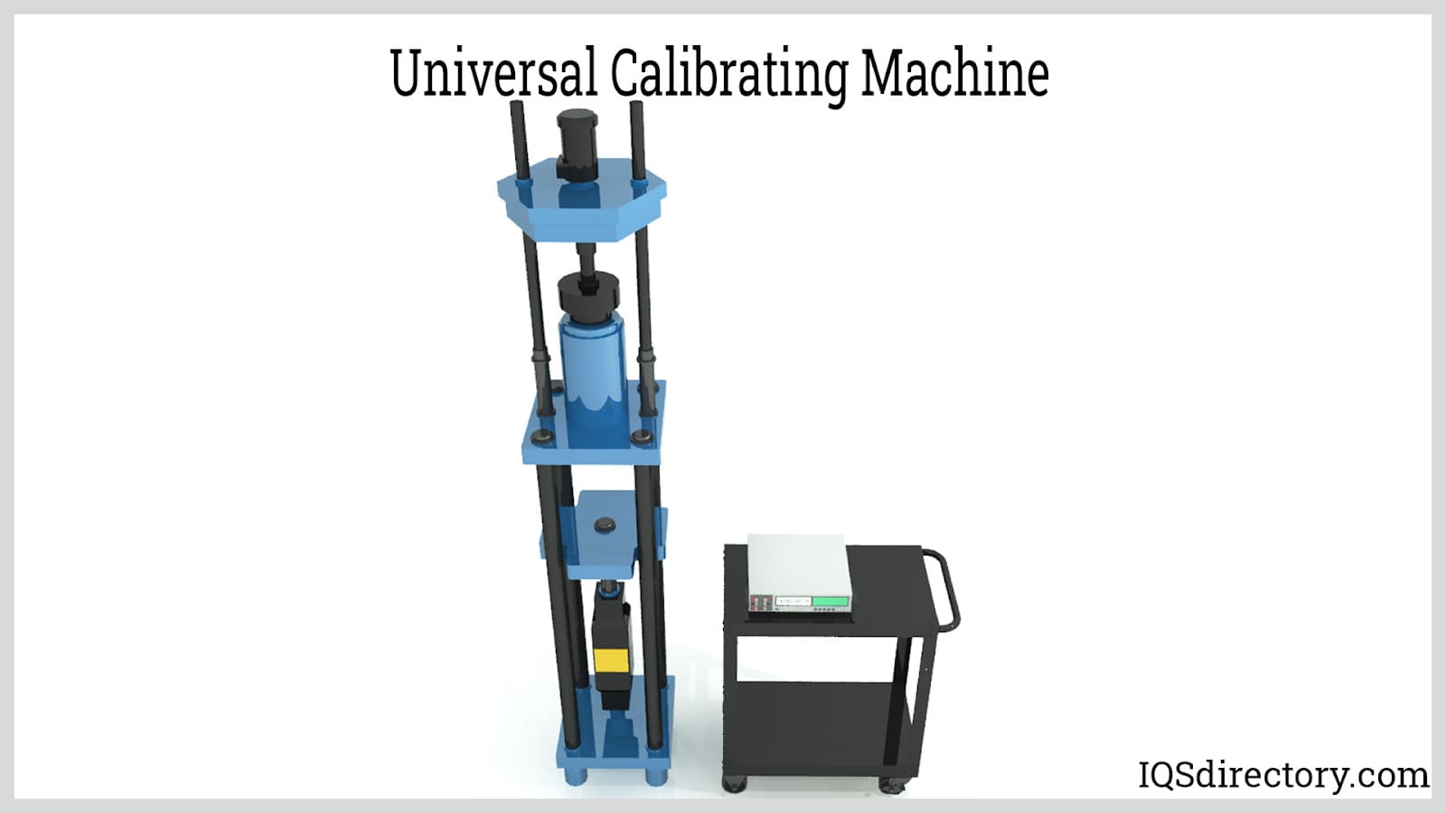
 Calibration Services
 Clean Rooms
 Data Acquisition Systems
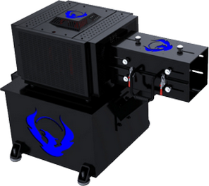 Dynamometers
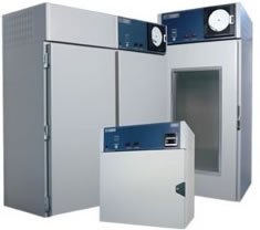 Environmental Test Chamber
 Leak Detectors
 Load Cells
 Machine Vision Systems
 Scales
 Thermocouples
 Castings & Forgings
 Bulk Material Handling
 Electrical & Electronic Components
 Flow Instrumentation
 Hardware
 Material Handling Equipment
 Metal Cutting Services
 Metal Forming Services
 Metal Suppliers
 Motion Control Products
 Plant & Facility Equipment
 Plant & Facility Supplies
 Plastic Molding Processes
 Pumps & Valves
 Recycling Equipment
 Rubber Products & Services